Sieve filters:
T- and Y-Strainers
(S8 and S9)
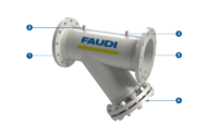
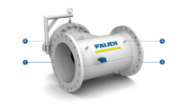
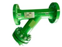
In chemical, petrochemical, refinery and power plant industries, fluid transport is realized through piping systems. A wide range of different forms of contamination occur in piping systems throughout all industries, either as a result of processes or due to aging and wear processes. Regardless of the fluid (gas, steam or liquids) flowing through the pipelines, sensitive plant components such as pumps, measuring and control instruments must be protected from such contamination. FAUDI strainers offer an economical and robust solution for applications with small amounts of dirt or where regular inspection is not necessary. The Y-strainer and T-strainer are named after the arrangement of the chamber for the dirt collection sieve. This branches off from the main line in either an angled Y-shape or a vertical T-shape. T-strainers are designed with a single sieve disc, while a sieve cylinder is used in a Y-strainer.
Benefits: Your advantages
at a glance
Cost-effective filtration solution
Highest achievable
filtrate qualitiesCompact and robust design
Particularly economical
at large volume flowsHigh design variability
Low pressure loss
Cleanable filter materials
In-line version
(version without height offset of
inlet & outlet)Horizontal or vertical
installation position possibleSuitable for liquids, gases and steam
How does a
Strainer work?
T-strainer:
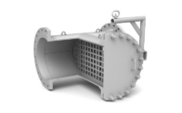
In a T-strainer, the flow is directed in a straight line through the filter housing. The fluid is injected through the inlet opening, flows through a strainer disc where contaminants are retained, and exits the filter housing through an outlet opening at the same level. The sieve disc is inserted into the housing by a third T-shaped outlet. Contaminants retained on the sieve disc create a differential pressure as they flow through. Increasing contaminants cause an increasing differential pressure. If a predetermined differential pressure is exceeded, the strainer disc must be removed and cleaned.
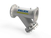
Y-strainer:
In a Y-strainer, the flow is injected into the filter housing by an inlet opening, flows through an inclined sieve cylinder in which contaminants are retained, and exits the filter housing through an outlet opening at the same level. The sieve cylinder is inserted into the housing by an angled outlet. The contaminants retained in the sieve cylinder cause a differential pressure during the flow. Increasing contaminants cause an increasing differential pressure. If a predetermined differential pressure is exceeded, the sieve cylinder must be removed and cleaned.

